Looking for the coaxial relay?
Looking for the cheap coaxial relay?
Looking for the cheap microwave coaxial relay?
Looking for the cheap microwave coaxial relay, but you don't like the latching type?
NO WAY you will find something like that!
If you are looking through the e-bay you can find a lot of offers for the high quality coaxial relays going up to 26 GHz. They are quite affordable and available. So where is the catch? They are all LATCHING type relays which should not be a problem if you know how to drive them.
.JPG)
.JPG)
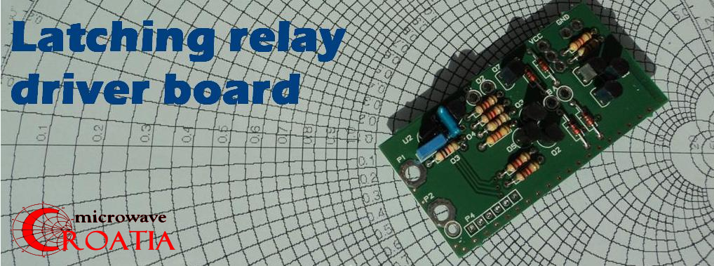
So this is the situation where our boards comes handy!
Just one board measuring only 65x32 mm can make all the job, driving all kind of the latching relays, depending on the bridge configuration that you setup on the PCB.
One board can drive or control:
- two coils positive pulse latching relay (12 V or 24 V)
- two coils negative pulse latching relay (12 V or 24 V)
- one coil reverse polarity latching relay (12 V or 24 V)
So how does it works?
Simple, you just need to ground (marked O4 on the PCB) the input PTT pad (marked O3 on the PCB), standard PTT option implemented on almost every radio output and the rest of the job is done by the board.
(There is also the possibility to use the positive voltage for the keying, but this modification, including 1 transistor should be done by the user, included in diagram)
(There is also the possibility to use the positive voltage for the keying, but this modification, including 1 transistor should be done by the user, included in diagram)
The 100mS power supply pulse (which is safe enough for many relay types) is then applied to one coil. Depressing the PTT or disconnecting from the ground the input PTT pad the same 100mS pulse is applied to the other coil of the relay.
So all you need to do is to connect the coils to the pads A and B and the common coil point to the VCC or to the GND point depending on the type of the relay you are using.
(Of course you need to setup the bridges on the PCB according to the user manual)
1. 2 coils latching relay common negative pole setup
 2. 2 coils latching relay common positive pole setup

1. 2 coils latching relay common negative pole setup
3. 1 coil latching relay reverse polarity setup
 Beside the two pulsed outputs (A and B) there are two other extra AUX outputs (O1 and O2) that can be used in different manner. You can use them to connect the LED to have a visual control of the relay state. The same outputs can be used also for driving the DC power to the transverter RX / TX so this board can simultaneously control the relay and the transverter, quite handy! You can use the same AUX output as the PTT driver for the other purposes.
.JPG)
The driver board is built around the ATMEGA-8 controller taking care of all logic's driving the open collector transistors capable of switching the 200mA up to 30V DC without any problem. This way the controller is isolated with a pair of NPN / PNP driver transistors (BC337 / BC327). Only the ATMEGA-8 is the SMD style and the rest of the board is using standard through hole components.
.JPG)
The boards are coming assembled and tested prior the shipping, together with the user manual with the description how to setup the configuration bridges (2 bridges) for the proper operation of the relay in question. The boards are built on the high quality FR-4 1.6mm double side laminate. The PCB is designed to fit the standard coaxial relays that are most common. This way the driver is occupying the limited space and can be mounted just on top of the relay in the application where the non latching coaxial relay are used.

Up to now, a decent number of boards are tested and checked from the various users around the world and none of them point to any problem regarding the safe operation. Beside that the design and the quality is really high. If you already had opportunity to test our products like LNA4ALL or HF-upconverter then you know what we are talking about.